
The sound of an audio system is most heavily influenced by the devices that generate the sound - the speakers.
Scroll the page, or select a topic below.
The Final Transducer

Basic Speaker Characteristics


Comb filter effect due to interference between direct
and reflected sound waves.
In Jan 2023, Joe Begin updated his 2019 article on The Keys of Loudspeaker Electroacoustic Measurements. This gives examples of the problems incurred when trying to get accurate measurements of loudspeaker performance. (Part 2) (Part 3)
Speaker Impedance

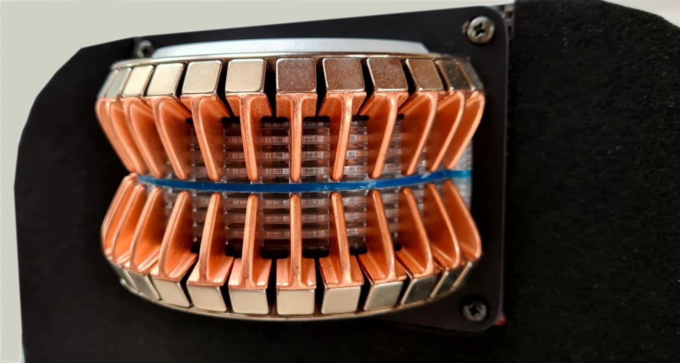
Speaker Driver Types


Constant Voltage Systems
When it is deemed necessary to use a large number of speakers, a Constant Voltage System is usually needed. Commonly called a 70-volt system, these systems are also used with 25 and 100 volts or even higher as well. Actually, these systems are more properly called Constant or High Impedance Systems, or High-voltage Audio Distribution Systems. but the older term is more widely used.
These systems use transformers to control the power to each speaker. The diagram to the left shows how this is done. While this shows a transformer at the amp, amplifiers can be designed to operat6e a constant voltage system directly. In most cases, the transformer at each speakers has taps for different power levels. As the diagram shows, each speaker can be set for a different power draw, but the total power needed to drive the speakers must not exceed the power capability of the amp driving the system.
- Much longer distances allowed for speaker runs
- Speakers don't affect each other's levels
- Smaller wire sizes can be used for distribution lines
- No complex series-parallel wiring
- Stereo pairs can use common ground line.
- Wikipedia has an excellent article on this subject.
- BiAmp has a detailed technical article on CV systems as well as an hour-long video on this topic.
- Lowell Manufacturing page on multiple speaker systems
- Common Questions Regarding 70-Volt Audio
- A Guide to Constant-Voltage Systems by Crown Engineering
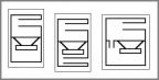
Speaker Enclosures

A Bose radio utilizing its waveguide design for improved bass response.

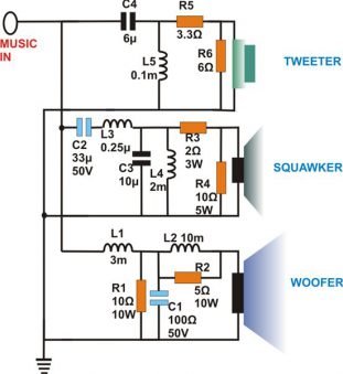
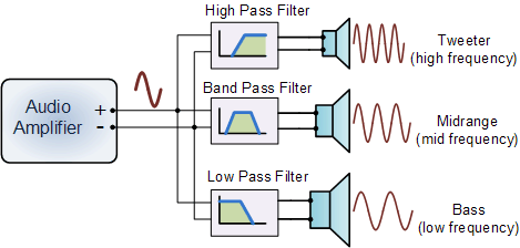
^ A 3-way Passive speaker Crossover Network ^

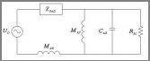
where ρ is the density of air (1.184 kg/m3 at 25 °C), and c is the speed of sound (346.1 m/s at 25 °C). Using SI units, the result will be in cubic meters. To get Vas in liters, multiply by 1000. Cms is the Compliance of the driver's suspension, in meters per newton (the reciprocal of its 'stiffness'). This illustrates how the enclosure must be matched to the characteristics of the driver. Consult Wikipedia for more details on TS parameters. An online calculator for TS parameters is here. More that 130 calculators for various design purposes can be found at HiFi Audio Design.
One thing Thiele found when developing his equations is that there is an inherent trade-off between box size, low-frequency response, and efficiency. You can design for any two but not all three at the same time. At the time, efficiency was very important due to amplifier power limitations, Now, with things like class D amps, efficiency is no longer as critical.
Alpha Sound produced a video in July 2022 that shows some interesting experiments with bass speakers. He demonstrates physically the effect of the bass reflex port. He also demonstrates the use of multiple speakers and digital delays to give a bass speaker some directionality and how two speakers can be set up to provide a cardioid directional pattern. An example is the QSC cardioid sub shown below.
Some Examples


^The ElectroVoice Sentry III Monitor Speaker^
^ The Martin Audio TORUS Speaker ^
v The AirBlade Tweeter v

^The Decwave D032 Dual Horn-loaded Subwoofer^
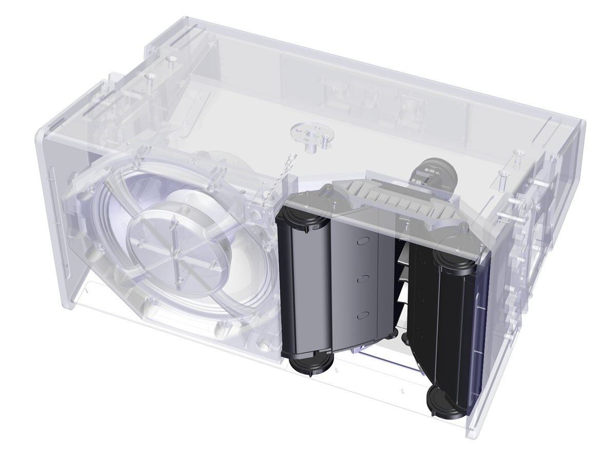
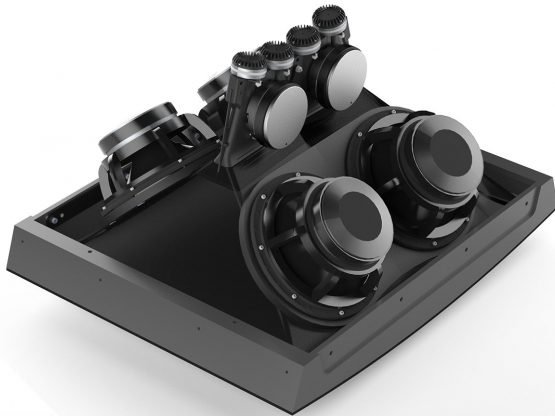
v The QSC KS212C Subwoofer v
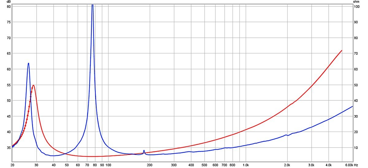
The QSC 212 is a subwoofer that uses two 12-inch drivers in a dual 6th order band-pass design to create a cardioid radiation pattern that provides 15 dB SPL attenuation front-to-rear . The trick is to use two drivers where one is out of phase with the other and delayed so as to achieve partial cancellation of the external rear waves from the two speakers. Sweetwater has a discussion of this topic.
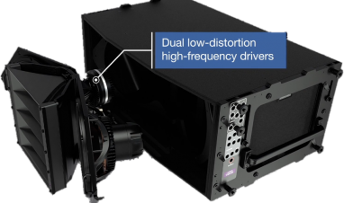
The 3,600 Watt KS212C subwoofer uniquely provides all the benefits of cardioid deployment in a single, compact enclosure. It measures 24.5 × 15.5 × 33.5 inches and weighs about 88 pounds. There are wheels on the back that aid in moving this monster around.
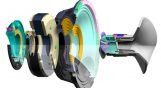
Professor Doug Jones of Danley Sound Labs gives a video explanation of what differentiates the Synergy Horn technology from more traditional approaches both current and throughout history. Examples of the technology can be viewed at the Danley Sound Labs website. Detailed papers on this technology can be found here and here. The basic design concept is also called A multiple Entry Horn ( MEH.) Another example of building a personal speaker based on this concept can be found here. A collection of links to similar designs can be found here.
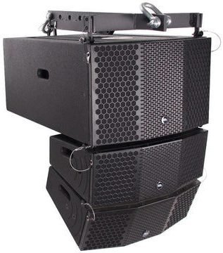
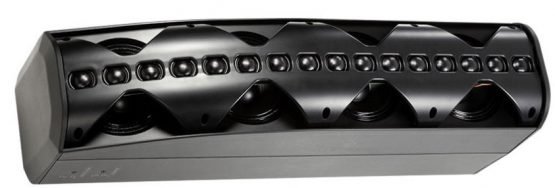
A line array is a loudspeaker system that is made up of a number of usually identical loudspeaker elements mounted in a line and fed in phase, to create a near-line source of sound. The distance between adjacent drivers is close enough that they constructively interfere with each other to send sound waves farther than traditional horn-loaded loudspeakers, and with a more evenly distributed sound output pattern. (Wikipedia Article on Line Arrays)
The line array effect of the narrowing of the beam with increasing frequency was first demonstrated by acoustical pioneer Harry Olson in 1957. In 1961, Jim Kyle designed and built a speaker system called the "Sweet Sixteen," the first line array for DIY hobbyists using sixteen 1 to 3-inch drivers in a vertical array. Since then, tremendous improvements to this technology have been made by almost all manufacturers of professional loudspeakers, and today they are very common in large indoor and outdoor venues. Most line arrays are supplemented with subwoofers, as shown here.
- Line Arrays Explained - The Science And The Magic By David Mellor March 2006
- John Murray (May 2009) has a 3-page article covering the basics on Line Arrays..
- Wired Magazine has an article on line arrays with a nice video explaining and demonstrating how they work.
- A famous musical artist convinced a major manufacturer of arrays to make their systems lighter. Here is the result. (The picture to the right.)
- The evolution of the Sweet 16 - the JBL CBT 70J-1 reviewed in detail.
Additional Resources
Speakers are a critical part of a sound system, and there is an abundance of information about them on the Internet;. Here are a selected few of them.

A fairly comprehensive article, with interesting history and examples. Lots of links to more resources.
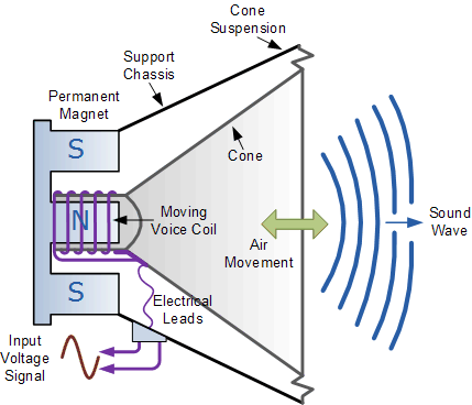
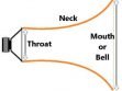
A basic introduction to sound propagation and transducers. Excellent diagram of a dynamic driver. (Used above.)


Robert Triggs of SoundGuys describes is some detail the importance of speaker response for the reproduction of music.


This aerospace engineer attempts to blend scientific measurements with objective observations of various audio gear. Excellent information resource. Impressive speaker measurements and observations.

This combines information from a number of sources on various aspects of audio technology. Lots of thoughts and opinions, some of which may be somewhat subjective, but this is a good source of information on audio topics.

The Absolute Sound website has a rather detailed article on loudspeaker types, their advantages and disadvantages.

This article covers all the basics on speaker crossover elements. No circuit diagrams, however.
Wikibooks has a detailed article on the use of TS parameters for enclosure design.
AmpLabs has a large number of speaker design projects where the details design of crossover and enclosure parameters are discussed.
AudioJudgement.com published an article in 2016 that discusses horn design for loudspeakers. A detailed three-part article on design of horn speakers by J. Dinsdale was published in 1974.
Several types of subwoofers systems are covered on this site, including sealed, ported, bandpass, passive radiator and transmission line systems. Very Comprehensive.

This site is a very comprehensive source of information on enclosure design and other AV topics. Has a nice page on resistor color codes. The speaker design calculator is somewhat limited.

This is an excellent $40 simulation program for Windows PCs. Covers most types of designs, has six types of crossover calculators and an expandable database of speaker parameters,
Christopher Grimshaw has published a A Series On Fundamental Loudspeaker Design. He quotes Hoffman’s Iron Law – small cabinet, efficient, low bass – pick any two. This is something we’re constantly working against. Spending more money on better drivers improves the situation, but there are still limits.
In 2013, Craig Leerman published an article on Loudspeaker Design Trends that shows some instances of the steady stream of new developments that get us closer to the “ideal” in addition to presenting new options.

In 2011, Rick Kamlet published an article discussing Ceiling Layout Patterns for Distributed systems.

David Kennedy published an article in 2019 in Front Of House magazine on Subwoofer Arrays to change radiation patterns. A detailed presentation is at DoctorProAudio.com. A designer spreadsheet for subwoofer arrays is also available.
Wikipedia has an extensive article on Subwoofers that also discusses subwoofer arrays and bass shakers.