Audio Concepts
Audio is a term used for the science of sound wave generation, recording, and reproduction. A wave is a repetitive movement of the molecules of a substance, the medium, caused by movement of an object or pressure from some external force. When a wave is able to be heard by a person or animal, it is called a sound wave. Sound waves are most often characterized by a sine wave or a combination of them.
Please Note!
The topics below are designed to be read in order, at least initially, as indicated by the numbers beside the topic. Admittedly, these are presented in very basic fashion, intended for those new to this field, but a good understanding of the basics of any technical field is essential for mastery of any topic. Reading them in the order suggested will benefit the reader.

A Sine Wave
The dictionary definition of a sine wave is a waveform that represents periodic oscillations in which the amplitude of displacement at each point is proportional to the sine of the phase angle of the displacement and that is visualized as a sine curve. A sine wave is a mathematical function characterized by its frequency and its amplitude. The frequency is the time it takes for completion of a single wave cycle. Frequency is stated as Cycles per Second or Hertz (Hz). The amplitude is the height or value of the waveform. Sound waves are measured in pressure units. In electronic circuits, this unit value is given in Volts. It is the measurement of signal level or loudness. For additional details regarding measurements, see the section on Power Ratings on the Amplifiers page.
Perhaps the best way to understand how sound can be characterized by sine waves is to view a video such as the one created by Mark Newman in 2015 - Sound As Sine Waves Another helpful video is Overtones, Harmonics and Additive synthesis by SynthSchool, 2010. This video introduces the concept of overtones or harmonics, which are multiples of the fundamental frequency of a sine wave. Some instruments, such as a flute, can produce a sound that can be represented by a single sine wave. Most instruments generate sounds that contain harmonics of a single wave or combinations of sine waves at different fundamental frequencies. It is these different combinations of sine wave sounds that characterize each instrument.
In 1822, French mathematician Joseph Fourier discovered that any wave could be modeled as a combination of different types of sine waves.
This applies even to unusual waves like square waves and highly irregular waves like human speech. The discipline of reducing a complex wave to a combination of sine waves is called Fourier analysis, and is fundamental to many of the sciences, especially those involving sound and signals. - wiseGEEK
The primary characteristic of a sine wave is its frequency. Frequency is measured in cycles per second, a unit which is now called Hertz, abbreviated Hz. (pronounced “hurts.”) The human ear can only detect sound waves whose frequency is between roughly 20 Hz and 20,000 Hz. Of course, not every person is capable of hearing that entire frequency range. Typically the sound range of most people is between 50 and 10,000 Hz, depending upon one's gender, age, and previous sound level exposure. Moreover, the human ear has a sensitivity that varies with frequency.
Human ears are most sensitive to frequencies between 2000 and 4000 Hz, and that sensitivity falls off at higher and lower frequencies. Our ears are also more sensitive to high frequencies than lower ones – low frequency sounds (below 200 Hz) must be louder in order to be heard at the same level as higher frequencies. Our hearing sensitivity is also a function of the loudness of a sound. The curves which express these relationships are called equal loudness contours or Fletcher-Munson curves, named after the men who first described these relationships in 1933. A good description of this concept is found at Wikipedia.
To take an example, look at the red 40 Phon curve. (A phon is a measurement of sound pressure at 1 kHz, expressed in decibels, dB. (See below to learn about decibels.) This curve indicates that at 100 Hz, for a sound to be perceived as loud as one at 1Khz, it must have a value of about 60 dB, and a sound at 10kHz must be at 55 dB. The dB values will be defined below, and you'll see that those differences are significant.
In general, frequencies below about 200 Hs are called bass, frequencies between 200 Hz and 2000 Hz are called mids, and all above about 2000 Hz are called highs. This is a somewhat arbitrary classification. The human ear has an amazing ability to perceive and adapt to sound levels in ways that are not completely understood. Because of this ability, the human hearing capability may span a range of 140 dB, but sounds above about 85 dB are considered damaging to the ear structures. See Stanford University Study for more details.

When a sound is reproduced by an electronic system that precisely represents the original sound, that reproduction is said to have “high fidelity” - it is an exact or faithful representation of the sound source. When the electronic system changes the sound from the source, its is said to have created distortion. If the distortion consists of primarily overtones of the source wave, the distortion is called harmonic distortion. If the distortion creates new fundamental frequencies, it is called intermodulation distortion (IMD). Harmonic distortion often goes unnoticed in typical audio signals, being masked by other sounds, but IM distortion is usually more evident, as it creates frequencies not part of or similar to the original sound. Special instruments can measure the amount of distortion created by an electronic circuit. A high-quality circuit has total distortion below 0.01% or less.
An oscilloscope or similar device is required to see or measure distortion. In practice, an audio engineer must detect distortion by listening. Most people cannot detect distortion below about 1% in a typical musical piece, although some audiophiles claim to be able to hear distortion when it reaches 0.1% or so. Some musical instruments, such as an electric guitar, are designed intentionally designed to produce IMD as part of its sound, but for the sound technician, the systems in use must minimize most forms of distortion.
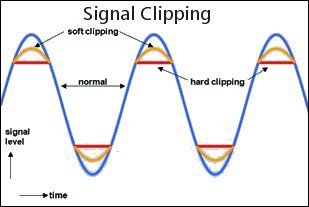
One particular source of distortion is signal overload. This occurs when the incoming signal is too great for the following circuit. This is called clipping. Most systems have some type of input level control to set the signal level so that it does not overload the amplification circuit. On a mixer, there are several stages where overload can occur if the level controls are not set properly.
One type of distortion that can occur with audio systems is phase distortion. When the waveform is somehow changed by the system without harmonic or IM distortion, it is usually called phase distortion. Many times, this is done on purpose by circuits that apply equalization. Equalization is a process of adding or removing specific frequencies from a sound to either make it sound more like the source or to give the sound from the source some desired audio properties – more bass or more treble, for example. Equalization generally introduces some phase distortion. Grossly changed phase relationships, without changing amplitudes, can be audible but the degree of audibility of the type of phase shifts expected from typical sound systems remains debated. (Wikipedia)
One source with more details on this topic is Understanding Audio Distortion.
David Williams also has a rather interesting article on Harmonics and THD in Audio Systems: Are You a Subjectivist or a Rationalist?


When electrons move through a conductor, the pressure or potential of the source is measured in volts, and the current – the amount or rate of flow - is measured in amperes, or amps. The resistance offered by the conductor to the flow of electrons is measured in ohms. An audio signal is a form of alternating current and the resistance is composed of inductive reactance and capacitative reactance. (Explained later.) These two are combined mathematically to give a resulting impedance, which is the resistance offered by a conductor to ab alternating current..
The relationships between voltage, current and resistance in a given circuit are represented mathematically by an equation called Ohm's Law
E = I x R,
where E is Voltage, I is current, and R is resistance. The power of the source that is created by the voltage applied to a resistance is given by the formula P = I x E
Power is measured in watts. From these two equations, it is apparent that power can also be expressed by
P = I x I x R
This equation can be used to calculate any one of the three circuit values from the other two values. For example,
I = E/R
The diagram to the right gives the equations for calculating the various parameters involved in Ohm's law. An online calculator for Ohm's Law can be found here.

One thing that new audio techs must get accustomed to is the use of logarithms. The definition is this: a quantity representing the power to which a fixed number (the base) must be raised to produce a given number. Logarithms are used to reduce the apparent spread of frequency and voltage values encountered in this field. For example, the figure used above to show equal loudness contours uses a logarithmic scale for the frequency values, as does the frequency response graph to the right. Without that, it is impossible to read the values from a graph that covers more than about 5 octaves. (An octave is a doubling of a frequency value.) The logarithmic graph is able to display values from 10 Hz to 20kHz, which covers almost 15 octaves. Amplitude values have the same problem. Audio signals can range from near zero to around 20 volts, which is an infinite range, but the lowest values measured are around 0.000001 volt (1 microvolt) to about 10 volts, which is equivalent to about 27 octaves. (Octave is a term not normally used with regard to amplitude values, however.) To express such a large range of values, a logarithmic function is used. To describe this function, let me use a quote from Wikipedia:
The decibel (symbol: dB) is a logarithmic unit used to express the ratio of one value of a physical property to another, and may be used to express a change in value (e.g., +1 dB or -1 dB) or an absolute value. In the latter case, it expresses the ratio of a value to a reference value; when used in this way, the decibel symbol should be appended with a suffix that indicates the reference value or some other property. For example, if the reference value is 1 volt, then the suffix is "V" (i.e., "20 dBV"); and if the reference value is one milliwatt, then the suffix is "m" (i.e., "20 dBm"). However, sound pressure level is referenced to the "threshold of hearing" (generally given as 20 micropascals at 1 kHz), and the suffix is "SPL" (i.e., "60 dB SPL"). The formula for the decibel value that relates two power values is
dB = 10xLog(P2/P1)
Here, P1 is called the reference value, and the Log uses the base 10.
Since voltage values relate to power values as a square root function, in order to be able to easily compare the two decibel values, the formula for voltage values is
dB = 20xLog(V2/V1)
To see how this works, let's calculate the decibel value for a 10-volt signal relative to 1 volt. The division result is 10, the log10(10) is 1, and the dB value is 20. Thus, a 20 dB value means that the voltage in question is 10 times its reference voltage. If this voltage were applied to a 1-ohm resistor, the resulting current would be 10 amps (I=E/R).
Now if this 10-volt signal were applied across a resistance of 1 ohm, the effective power, for the same current value, would be 100 watts. (P=IxIxR), and the 1-volt signal across the 1-ohm resistor would create a 1-amp current and a power value of 1 watt. The resulting power ratio would be 100/1, and the log10 (100) is 2, so the resulting dB value would be 20.
So we see that the dB calculations give the same result whether the amplification is calculated based on voltage or power. This little mathematical excursion may seem drawn out, but it is very important to have a feel for voltage and power numbers expressed in this way, since most amplitude values are expressed in dB in practice. For example, look at how the faders (sliders) of a typical mixer are labeled. The scale is sometimes linear, but the values are logarithmic. That's because the underlying variable resistance controlled by the fader has a logarithmic contour. At the lower positions of the fader, each unit of movement produces a greater change in its output than when the slider is at the upper positions. At the 0 dB position, the output signal is equal to the input signal, so some mixers label this position as U, for unity gain. Notice that the fader covers about a 70 dB range.
In terms of voltage, if the mixer is rated at 1 volt out with the slider at 0 dB, the slider covers a range from +10 (~3 volts) to -60 (0.001 or 1 millivolt. That represents power values of 10 watts down to 1 microwatt (10^-6 watt). Also remember that multiplication of two numbers can be accomplished by adding their logarithms. Thus if voltage of 10 volts (20dBV) is amplified 10 times to 100 (40dBV) you get the same result by adding 20dBV + 20dBv = 40dBv. Most often, the sound technician uses dB to measure differences in sound levels, so the reference voltage or power need not be known. We'll come back to this point when we discuss mixers elsewhere.
It is also useful for a technician to keep in mind what a few decibel numbers represent. A great table for seeing these values is found at Wikipedia. Note that a +3 dB change doubles a power value and is about 1.4 times a voltage value. A 10 dB difference is 10 times a power value and about 3 times a voltage value. A 20 db difference represents 100 times a power value and 10 times a voltage value. One site that has an informative page about Decibels is Physclips. Here, you can hear differences in sound levels measured in decibels and learn more about the topics presented above. Also see the article on decibels at Boundless.com.


In general, a transducer is a device that converts one type of energy into another. Common examples in the audio field include microphones, loudspeakers, position and pressure sensors or devices, and antennae. A piano keyboard, a guitar, and a drum are transducers that change mechanical energy into sound waves. A horn or a
clarinet converts vibrational energy into sound waves. Of course, sound waves are a form of vibrational energy (vibrating air molecules, e.g.), and transducers are needed to convert these into electrical signals.
A microphone is a transducer. A piezoelectric device that converts sound pressure waves into an electrical signal may be called a microphone or a piezoelectric transducer. These are often used with guitars and pianos to convert their sound into electrical signals that can be amplified. An electronic keyboard converts mechanical movements directly into an electronic signal. The needle used in playing a vinyl record converts mechanical movement into an electrical signal. Speakers and
low-frequency vibrators convert electrical signals back into sound waves. An antenna converts high-frequency electromagnetic waves into electrical signals and vice-versa.
An audio speaker is a device that uses a coil of wire moving in a magnetic field to convert electrical signals into sound waves. Other transducers, such as guitar pickups, dynamic microphones, or phonograph cartridges, sense vibrations using a magnet inside a coil of wire to convert vibrational energy into an electrical signal. Most of these devices are inherently zero-distortion devices, but if not constructed properly or operated out of their design range, they can produce serious distortion. So a sound engineer needs to know enough about these devices in general and about some in specific detail to ensure that they are operated properly. The engineer must also know what type of microphone or sound pickup device is best for each particular instrument and situation, what problems may arise, and the costs involved. Some of this will be covered elsewhere on this site. See the sections on Microphones and Speakers.
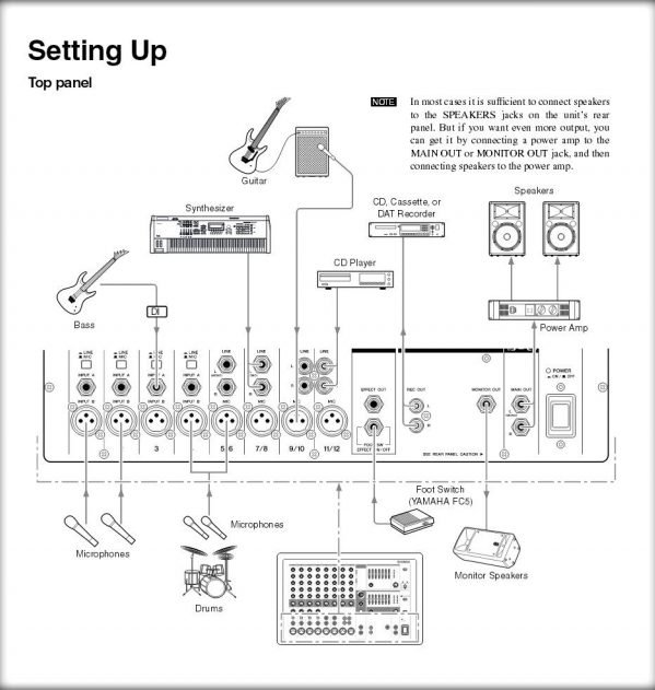
All sound systems generally require these basic elements:

- The sound source can be anything that generates an electronic audio signal, Examples are microphones, CD players, MP3 players, guitar pickup or keyboard.
- Some devices, such as microphones, require a preamp to boost the signal to a level that the Control section can handle,
- The Control section can consist of many types of controls. Examples are signal level, frequency modification (EQ), compression, effects (FX), and signal routing.
- Next is a Power Amplifier to convert the voltage from the control section to a high-current signal that can drive the Speakers. Powered Speakers contain their own amplifiers.
The type of components needed for such a system depends on the situation in which it is used. Some examples include:
- A basic DJ system
- A simple PA system
- A home audio system
- A church worship system
- A complex indoor sound system
- A complex outdoor sound system
- A conference room sound system
- A commercial building distributed sound system
A technician using each of these systems must know how each of the elements that make it up function and how to operate them properly. The rest of the pages in the Audio section of this site provides these details.
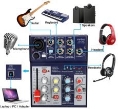
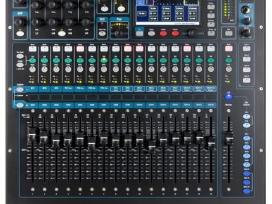
The most common Control element is a Mixer. This is component contains a preamp and several other controls, depending on its complexity. Its function is to process the signal from each input source and combine these signals into those needed to drive the outputs. An Analog mixer processes all signals as discrete sound waves. A Digital mixer converts the signals to digital packets that are processed with digital circuitry. A Hybrid mixer is an analog mixer that incorporates some form of digital circuitry to carry out certain functions, such as FX. Most digital mixers have some type of LED display that typically incorporates touch functionality to carry out some of its operations. These screens can show EQ curves and metering, for example.
An Analog mixer may have Insert jacks after the Preamp that allow external processors such as EQ and/or Compression to be added to the signal chain. Most digital mixers have these functions built in, so they usually do not have Insert jacks.
Most digital mixers can be operated remotely over WIFi using a tablet or smart phone. This adds to their functionality in a significant way. Digital and Hybrid mixers also usually have the ability to send signals via USB or Firewire to a computer, where the individual channels can be processed using Digital Audio Workstation (DAW) software.
Sweetwater has a good article that presents the Fundamentals of Live Sound. This paper discusses the various types of sound systems and provides details on the many technical considerations that must be understood to properly design and use a sound system. Links are provided to additional resources. (March 14,2022)
Use the links below for more information available on this website on the specific topics listed.


