Audio Power Amplifiers
[Amp Classes]-----[Amp DSP]-----[ Constant Voltage]-----[Output Impedance]-----[Power Ratings]
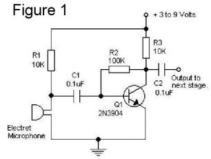
The final device in an audio amplification train or system is almost always some type of amplifier. Figure 1 is a circuit diagram of a simple transistor amplifier. This one is used to amplify the sound from an electret microphone. The small voltage signal produced by the microphone is amplified to a higher voltage so it can be processed by subsequent circuitry. An amplifier used in this way is called a Pre-amplifier. These can be very simple, like this one, or very complex, depending on its purpose. One thing to note is that resistor R2 is used to bias or turn on the transistor so that it will amplify the incoming signal. The capacitor at the input and output is used to isolate the part of the circuit from any DC voltages that may be there; it will pass only an AC signal, such as an audio signal.
Note: This presentation will be only about Analog amplifiers. Digital amplifiers work differently, but some of the principles discussed here may still be applicable.
A typical audio preamplifier (preamp) usually has several stages. The first stage is designed to present a proper load (impedance and current) to the input device and bring up the voltage to a value that can be used by subsequent circuitry. The next stage may be a special equalization circuit, designed to tailor the frequency response of the signal. This stage may be passive or active, the latter requiring an amplifier itself. Subsequent stages may be a dynamics processor, such as a compressor, or something else. Each stage of amplification must be designed to minimize any noise or distortion that may be added to the signal. A Power Amplifier is used to increase both voltage and current. Power amplifiers are usually designed to operate with input voltage around 1 volt. As stated above, some type of preamp, such as a mixer, must be used to boost the output from microphones and guitar pickups to a level suitable for a power amp. Pro devices have output levels around 1.2 volts, but non-pro (Home) devices typically generate less than 1 volt, around 0.3 volts. Sweetwater has an article that discusses this in some detail.
Amplifiers are grouped into classes according to their construction and operating characteristics or circuit topology. The main operating characteristics of an ideal amplifier are linearity (lack of distortion), signal gain, efficiency and power output, but in real world amplifiers there is always a trade off between these different characteristics. Amplifier classes are mainly lumped into two basic groups. The first are the classically controlled conduction angle amplifiers forming the more common amplifier classes of A, B, AB and C, which are defined by the length of their conduction state over some portion of the output waveform, such that the output stage transistor operation lies somewhere between being “fully-ON” and “fully-OFF”. The second set of amplifiers are the newer so-called “switching” amplifier classes of D, E, F, G, S, T etc., which use digital circuits and pulse width modulation (PWM) to constantly switch the signal between “fully-ON” and “fully-OFF” driving the output hard into the transistors saturation and cut-off regions. (Source)
Class “A” amplifiers are considered the best class of amplifier design due mainly to their excellent linearity, high gain and low signal distortion levels when designed correctly. Although seldom used in high power amplifier applications due to thermal power supply considerations, class-A amplifiers are probably the best sounding of all the amplifier classes mentioned here and as such are used in high-fidelity audio amplifier designs. However, at power levels above about 20 watts, Class A amps generate so much heat that they are seldom practical. Because of this, most high fidelity amps have resorted to what is termed Class AB design.
In Class B amplifiers, separate amplifier circuits are used to drive the "upper and lower portions" of the audio signal. (Above and below the zero level of a typical sine wave.) This divides the power between two power transistors, but at the crossover point, considerable distortion is created, so such an amp is not suitable for good quality audio. The Class AB design was developed to overcome the problem of strict Class B by providing a small bias current that keeps both power transistors on near the crossover point. Since the late 60's most hi fidelity amps have been designed around various Class AB topologies. This has changed significantly as Class D topology technology has improved since the 90's.

In Class C amplifiers, the bias point is placed well below cut-off, so the transistor is cut-off for most of the cycle of the wave. This gives much improved efficiency to the amplifier, but very heavy distortion of the output signal. Class C is therefore not suitable for audio amplifiers. It is however commonly used in high frequency sine wave oscillators and certain types of RF amplifiers, where the pulses of current produced at the amplifier output can be converted to complete sine waves of a particular frequency by the use of LCR resonant circuits. (Source)
In class D audio amplifiers, the basic operation of which is shown in to the right, the audio signal is first converted to a type of digital signal called ‘Pulse Width Modulation’. This is not a digital signal within the normally accepted definition of ‘Digital’ regarding recognized logic 1 and 0 levels, but only in that it has two levels, high and low. When such a signal is amplified, very little power is dissipated in the amplifier, as when the output transistors are ‘on’ and passing their maximum current, there is practically no voltage drop across them and therefore (as Power = Voltage x Current) there is practically zero Power. Likewise, when the transistors are ‘off’, a large voltage is present but no current is flowing. This results in much greater efficiency than in conventional analogue amplifiers. The PWM output signal is finally converted back into analogue form at the output. (Source)
According to Wikipedia, The first Class-D amplifier was invented by British scientist Alec Reeves in the 1950s and was first called by that name in 1955. Practical class-D amplifiers were later enabled by the development of silicon-based MOSFET (metal-oxide-semiconductor field-effect transistor) technology. In 1978, Sony introduced the TA-N88, the first class-D unit to employ power MOSFETs and a switched-mode power supply. The availability of low-cost, fast-switching MOSFETs led to Class-D amplifiers becoming successful in the mid-1980s. The first class-D amplifier based integrated circuit was released by Tripath in 1996. Since then most technical issues with Class D topology have been solved, so that today, Class D is the most popular design for professional power amplifiers, particularly those incorporated directly into speaker enclosures.
The major advantage of a class-D amplifier is that it can be more efficient than a linear amplifier, with less power dissipated as heat in the active devices. Given that large heat sinks are not required, Class-D amplifiers are much lighter weight than class A, B, or AB amplifiers, an important consideration with portable sound reinforcement system equipment, bass amplifiers, and automobile sound systems.
Amplifier classes such as E and F are basically enhancements of class D, offering more complex and improved output filtering, including some additional wave shaping of the Pulse Width Modulation signal to prevent audio distortion. Classes G and H offer enhancements to the basic class AB design. Class G uses multiple power supply rails of various voltages, rapidly switching to a higher voltage when the audio signal wave has a peak value that is a higher voltage than the level of supply voltage, and switching back to a lower supply voltage when the peak value of the audio signal reduces. By switching the supply voltage to a higher level only when the largest output signals are present and then switching back to a lower level, average power consumption, and therefore heat caused by wasted power is reduced. Class H improves on class G by continually varying the supply voltage at any time where the audio signal exceeds a particular threshold level. The power supply voltage tracks the peak level of the signal to be only slightly higher than the instantaneous value of the audio wave, returning to its lower level once the signal peak value falls below the threshold level again. Both classes G and H therefore require considerably more complex power supplies, which adds to the cost of implementing these features. (Source)
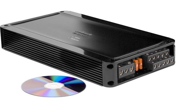
As an example of class D technology, I have selected the Polk PA D5000.5 automobile amplifier. This compact 900-watt amp (14x2x6.75 inches) will drive 5 speakers (4 x 100 watts, 1 x 400 watts. 2-ohms each) weighs 4.4 pounds and runs on 12 volts. Rated distortion is <0.1% THD. It has on-board DSP - high pass filters for 4 amps and low-pass filter for the sub channel, all with variable gain. The sub channel will even operate as low as 1 ohm, where it can generate 500 watts.
A Class D Integrated Circuit Amp
Texas Instruments has introduced the TPA3116D2 chip that contains 4 separate Class D power amps arranged in pairs. The IC contains circuitry that protects the amps from most types of load faults. Typically, these would be set up by external circuitry so that each pair would be bridged to create two amplifiers rated at 50 watts each into 4 Ohms. However, these two amps could also be set up in bridged mode to create one amp rated at 100 watts into 2 Ohms. Thus, two chips could be placed on a single circuit board with proper heatsinks to create a 100 watt/channel stereo amp fairly inexpensively. Fosi Audio is one firm that sells such an amp on Amazon. Go here for some application examples, and here for a TI evaluation module. ElCircuit.com has several application examples. I would caution an inexperienced builder - utilizing this IC is not entirely straightforward. I mention it here to show how Class D amplifier technology has progressed.

In some amplifiers, the preamplified signal may feed a Digital-Analog Converter (DAC) that converts it a digital signal for special processing. Such a circuit is called a Digital Signal Processor, or DSP. A DSP can be used for many different purposes and help maintain a high signal/noise ratio. Common uses for DSP are Equalization, Crossover, and Limiting functionality. Eventually, the digital signal must be converted back into an analog signal by another DAC before it can be heard. The Crutchfield PA Amplifiers Buyers Guide has a couple of videos that show the DSP settings for a Crown XLS and a Yamaha PX3 and the flexibility the DSP provides.
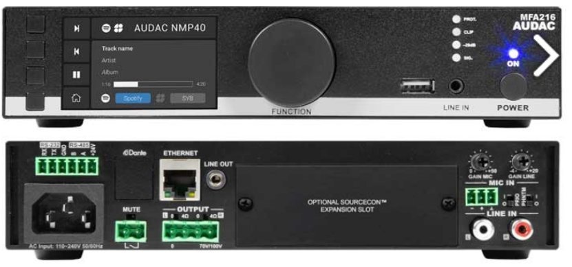
An Example - The Audac MFA 216
One example of an amplifier with integrated DSP is The Audac MFA series. The MFA 216 multi-functional amplifier is designed as a two-channel amplifier using class D amplifier technology. It can be used for powering low impedance stereo systems with a maximum power of 2 x 80 Watts, and bridging to a constant voltage (100V and 70V) is possible with a maximum output power of 160 Watts. Here is a functional diagram of the MFA 216:

This amplifier features a 7-Band fully parametric equalizer with adjustable frequency and Q-factor and Butterworth, Bessel, and Linkwitz-Riley filters with selectable roll-off. The diagram shows the DSP functions available using a dedicated application interface that allows it to be used in a wide variety of acoustic applications. Configurations also allow you to bridge the outputs, double the output power of stereo channels to one mono channel or make a single two-channel amplifier driving a complete setup composed of stereo Mid/High-frequency speakers and a bass cabinet. All of this functionality is made possible by a flexible DSP built into the unit.
For systems that require a large number of speakers but don't need to play very loud, a “distributed” system can be used. Here, the amp has been designed to provide a set voltage (typically, 25, 70, or 100 volts) to speakers that in turn have transformers set for particular loudness levels. In this case, the total power (Watts) required by all the speakers cannot exceed the power that the amp can deliver. These systems can provide excellent sound quality, depending on the speakers used, but the transformers can limit the low frequency performance. Wikipedia has an excellent article on Constant-Voltage Speaker Systems.
Every amplifier stage is designed to drive a subsequent stage or device of a given impedance. (Recall that Impedance is the resistance offered to an AC signal, such as an analog audio signal.) With an amplifier designed to increase the voltage level of a signal, connecting it to a device that is does not match its impedance simply results in either less signal (impedance much too high) or a distorted one (impedance too low.) The latter situation is the one to avoid, particularly with power amps.
For example, a guitar transducer is usually a low-current device designed to feed a high-impedance circuit, around 1 MegOhm or more. If it is fed to a circuit with a lower impedance, it will not be able to produce as much voltage signal because it can't provide the current required for that voltage across the lower impedance load.
Audio power amplifiers are usually designed to drive a speaker load whose total impedance is between 16 and 2 ohms. If the load is above 16 ohms, the amp will just not get as loud as with its proper load, but if the impedance is too low, the higher current can destroy the amp circuitry. For this reason, most power amps have some type of circuitry to protect it from low-impedance loads. Thus, if you try to drive a load whose impedance is too low, the amp will usually just switch itself off. Some may blow a protective fuse.
Thus with power amps, it is critical to match the speaker load to the designed impedance level for the amp. Of course, I am simplifying things here. A typical audio speaker impedance has three components of impedance – resistive, capacitive, and inductive – and these must be in proper ranges. For example, Certain speakers – electrostatic – produce a highly capacitive load, and not all power amps can drive them effectively. In most audio systems, we are dealing with speakers and amps that can work together effectively as long as they have a basic total impedance match.
Some care is needed when looking at amplifier power ratings. Several "conventions" are used in these specifications. This section is just a brief overview of this topic. Some links will be given below to more detailed articles.
Most of the measurements are based on the use of a pure sine wave as the input signal, and most often a 1 kHz sine wave is used. In order to get a feel for the ability of the amp to perform at a giver rating over the entire frequency spectrum, that range should be included, and the deviation from the 1 Khz level should be indicated. Thus, the statement should read something like this:
100 watts (RMS) , 20 Hz to 20 kHz (- 3 dB) at 0.3% distortion
Note that this rating is stated in terms of RMS watts. That brings up the other question that one needs to ask: What Watts? "RMS Power" is simply the product of RMS Volts time the current being applied. The RMS voltage is equivalent to 0.707 times the peak voltage of a sine wave signal. Using the RMS value allows us to use Ohms Law calculations, which are based on DC circuits. Instruments are available that can read Peak or RMS voltage values.
Peak power should be based the peak voltage of the sine wave, but it is often stated as twice that value - the Peak-to-Peak level. Unscrupulous manufacturers sometimes use this to inflate their product's performance. Some refer to the power based on the peak voltage measurement as Instantaneous Power. All of these terms are meaningless in real applications, since a real audio signal has to last a finite amount of time to be heard. An excellent explanation with good drawings is at TestGuy. See the video RMS Value of AC Circuits for another good explanation of these terms. Other explanations are presented here, and here
Another term often used is Music Power. The music power of an amp is real, and is generally higher than the continuous power. It is measured by using a tone-burst generator, and is the peak power than an amp can supply for (typically) about 10ms. This is quite reasonable, but not terribly useful when it is examined carefully, as music signals can vary substantially. To be consistent, most professional amps are rated using RMS watts, so that it is easier to make calculations in determining proper load values and performance.
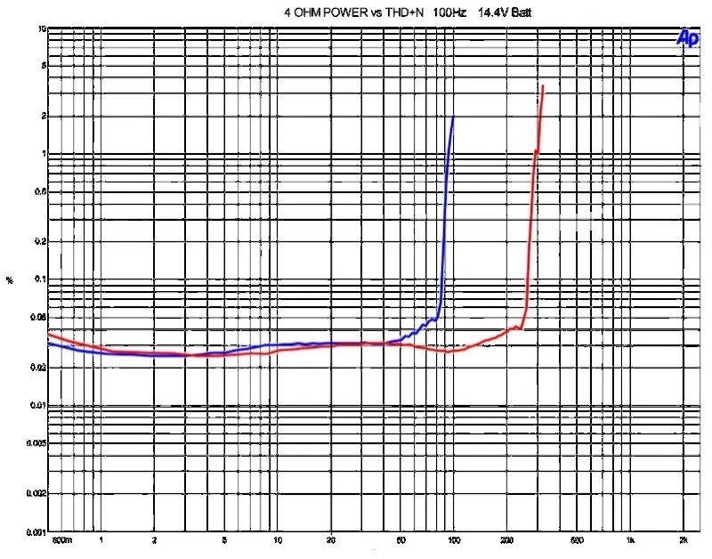
The next question is: What is the distortion level? The figure to the right shows what happens as signal level is increased in an amplifier. This shows distortion vs power. At most signal levels, the distortion is low for a high0quality amp, typically less than 0.05%. At some point, the distortion starts to increase dramatically, The amps shown in blue is rated at 90 watts at 0.3% distortion, while the one in red is about 270 watts at 0.3% distortion, Most people cannot hear harmonic distortion when the level is at or below about 1 percent, so some manufacturers use this level of distortion for their measurements, A better practice is to use a value of 0.1%, but most often a level of around 0.3% is used.
The third question is: How many channels are driven simultaneously?
While the power supply may be able to provide the stated power for one amp, it may not be able to do so if it also supports two or more channels.
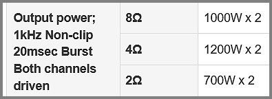
And finally, one must ask: At what Impedance? Most non-pro amps are rated at 8 Ohms. Pro amps are usually rated at 2 and 4 ohms as well. Typically, an amp can generate more power into a lower impedance, but the amp must be able to put out the additional amperage required to do this without burning out. So the power rating is usually indicated as Continuous or Instantaneous. The table to the right is an example of ratings from one manufacturer. Note in this case that the rating at 2 ohms means that the cooling system allows the amp to generate just a little more than half the power than at 4 ohms. The Burst signal makes this more of a Music Power rating at a moderate distortion level.
It is not that unusual for a pro amp to be left on for extended lengths of time, overnight or longer, so so the amp should be able to remain on for long periods without an input signal.. It isn't unusual for a church audio tech to go home after a service and forget to turn off the amps, for example, or a hospital announcement system must function continuously. Some amps can reduce power consumption automatically when a signal is not present, such as those inside a speaker cabinet.
Joe Roberts has an excellent article that covers most of the technical details - Audio Power Amplifier Power Rating Mysteries Explained
Crown has an excellent article on power ratings - How Much Amplifier Power Do I Need?


^ A basic 3-channel amp for use in an automobile ^
Online Resources
Measuring Amplifier Performance
Texas Instruments has a detailed Guideline for Measuring Amplifier Performance.
PA Amplifier Buyers Guide
Crutchfield has a basic but useful Buyers Guide that discusses how to choose a professional-grade power amplifier for your PA system.
Bridged and Paralleled Amplifiers
Wikipedia has a basic article on ways multiple amps can be connected to increase the amount of power available in different situations.