Directivity Diagrams
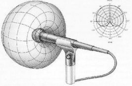
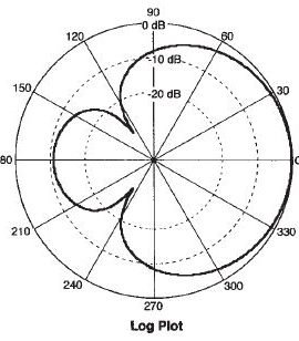
The directivity characteristics of a microphone or speaker are generally shown using a polar pattern diagram. This is basically a two-dimensional slice through the center of a 3-dimensional structure, along the axis of the microphone.

The curve in this diagram shows the relative signal level as a function of its angular direction from the center of, in this case, the microphone capsule. The levels are evenly-spaced concentric circles around the center point. The front of the capsule is at 0 degrees, shown as the 0 dB point for this microphone. At the rear of the capsule, 180 degrees, the signal level generated by the microphone is about -11 dB. At 60 degrees and 300 degrees, the sensitivity is -3 dB. The nulls are at 122 degrees and 238 degrees.
The diagrams below show the polar patterns for 5 types of microphones.


Notice the following features:
- The cardioid pattern has the highest rejection at the rear but a somewhat broader spread than the other types.
- The Supercardioid the Hypercardioid patterns are slightly more directional but have more sensitivity at the rear.
- The Supercardioid has rear nulls at approximately 115 degrees and 245 degrees. (360 degree spec.)
- The Hypercardioid has rear nulls at approximately 105 degrees and and 255 degrees. (360 degree spec.)
- The Bidirectional or Figure 8 pattern has equal sensitivity front and rear, and the pattern is more directional than the others.
This type is often used to mic two instruments in close proximity to one another.
- It is important to know the directional pattern of a microphone when placing speakers near them and when aiming the mic at a source.
- Vocalists should know what type of mic they are using so they know its sensitivity to the direction to his/her mouth.

