An in-depth knowledge of electronics is not necessary to be a successful audio engineer, but a basic understanding of certain concepts is very beneficial.
An engineer needs to know what type of connector to use for every device placed into service.
The ability to understand circuit diagrams and component flow diagrams is important.
Connectors and Adapters
Why Use Balanced Connections?
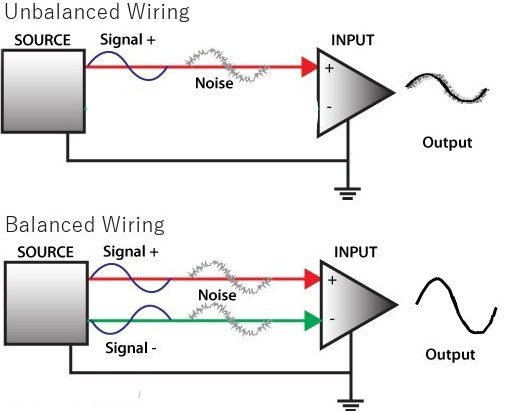
Balanced vs Unbalanced Connections
An Unbalanced connection has one signal wire and one ground wire that serves as a voltage level reference and often also as a shield against interference. Any noise induced in the signal wire will appear in the terminating circuit.
A Balanced connection has two signal wires, with the second signal being of opposite polarity (180 degrees out of phase) to the first. Any noise induced in the connection will appear on both signals. At the receiving circuit, the second signal is inverted and added to the first signal. This doubles the level of the signal and subtracts out all the noise.
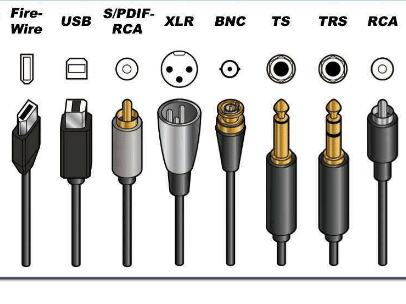
Types of Audio Connectors
(Click here for an overall diagram of connectors.)
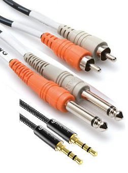
Unbalanced Audio
These types of cables are generally used to connects line-level devices to each other or to a mixer. At the top are RCA plugs. Below that are quarter-inch (6.35 mm) phone plugs, and then eighth-inch (3.5 mm) mini-stereo plugs. Most devices that use these generate stereo audio, and mixers that have jacks for them are always stereo channels.
Speaker Connectors
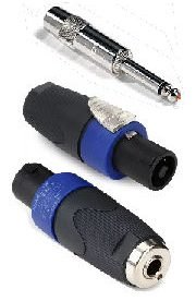
These connectors are used where higher current levels are required. The top is a standard quarter-inch phone plug, below that a Speakon plug, and finally an adapter that connects a standard phone plug to a Speakon jack. You will seldom see any other type of speaker connection in Pro audio.
Some helpful resources about audio connectors
Some Common Adapters
There are many adapters that come in handy from time to time for an audio tech. Some are direct adapters, that just switch from one type of connector to another. Others are impedance-matching adapters, that use a transformer to permit connecting a device with one impedance to another with a different impedance.
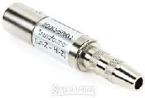
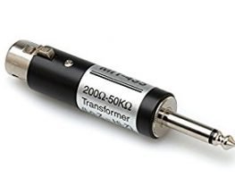
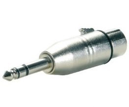
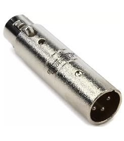
Four common adapters are pictured below.
XLR Male to Quarter-inch Female Transformer Adapter
With a quarter-inch unbalanced male/male cable, this adapter lets you connect a line-level device to an XLR microphone input.
XLR Female to Quarter-inch Male Transformer Adapter
This adapter is used to connect a low-impedance microphone to a High-Z input device. It could also be used to connect a line-level quarter-inch output to a Low-Z input, if an XLR male gender-changer is used.
Quarter-inch TRS Male to XLR Female Direct Adapter
This adapter is used to connect a XLR output from one device to another device that has Balanced TRS inputs, typically using a standard M/F XLR cable.
XLR Male to TRS Male Direct Adapter
This adapter is used to connect a TRS output from one device, such as the Aux Out from a mixer, to another device that has XLR inputs, such as a powered speaker, using a standard XLR cable.
Circuit Diagrams
A Few Examples
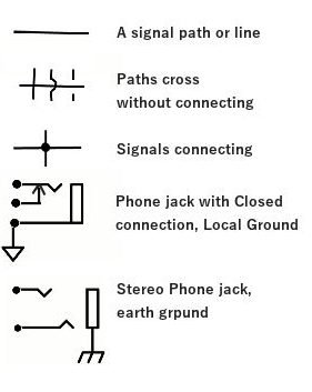
The ability to read circuit diagrams, also called Schematic Diagrams, is a very helpful skill for an audio tech, as these diagrams can consolidate a tremendous amount of information in a rather basic picture. A few simple examples are given here.
The picture to the left shows that a single line stands for an audio signal or DC circuit path. The diagram does not actually represent how the signals physically flow in the device itself. On a diagram, lines often cross without there being an actual connection. Three ways this is typically shown are given here. A solid dot or circle where the lines cross means an actual connection is made.
Next are a couple of ways that phone jacks may be pictured. The top one shows a jack for a single signal with a closed-circuit switch and a local or circuit-board ground. The other shows a stereo jack with an earth or chassis ground connection.
The figure to the right shows some common symbols used for electronic components in circuit diagrams. These may vary slightly from one author to the next, but they usually are slight variants of these symbols. Of course, there are quite a number of other circuit components not shown here. These are the most common.
The link below is to a site that gives a comprehensive description of circuit symbols.

As an example of what one can determine from a circuit diagram, consider the simplified flow diagram shown here. This is a partial diagram of the inputs of an audio mixer. This is not a complete circuit diagram, just the audio flow diagram, so electronic components are not shown. Here are the things this diagram shows:

Hum and Noise

Ground Loops
Hum is one the most frequently encountered types of noise in an audio system. The cause is usually a Ground Loop connection between two devices, such as a CD/DVD player and a mixer. It is very common when PC audio is connected to a mixer.
For safety reasons, every device powered from a standard electrical outlet must be properly grounded. Typically, the metal chassis of the device is connected to the electrical ground connection. The metals jacks used by the connectors on the device are usually grounded to the chassis. When two devices are connected together, their chassis connections must be at the same voltage potential, something very close to zero volts. If this is not the case, a very small electrical current can flow in the ground connection between the two, creating an 60-Hz signal in the connection. Typically, this signal is very small, but if the audio signal is also very small, the hum can be very noticeable, and its level is amplified every time the audio signal is amplified. Mike Sokol has an article om the Serious Business of proper grounding.
There are several common steps that can be taken to eliminate or minimize hum in an audio system. The following list is from a 5-minute YouTube video:
- Connect all devices to the same breaker, preferably to the same outlet.
- Use Balanced Connections wherever possible
- With Unbalanced connections, use a transformer isolator.
- Use audio chokes when needed and if effective.
- Use audio filters (EQ) to minimize the effect of the noise
Hum and crackling noise can results when there is an intermittent break in the signal wire of a cable or plug, or in the shield. The break must be identified and repaired or replaced. Sometimes, the hum can come from the power supply in a device. If the supply has inadequate filtering, or if its filter capacitors have deteriorated, hum can result. Due to DC rectification, this hum is now at 120 Hz. This can be very difficult to remove. Repair the power supply, replace the device, or try some EQ to minimize the noise.
Three Tools for Eliminating Ground Loop Hum
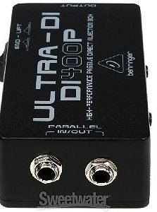
A Passive DI Box
A Direct Injection (DI) Box is a good way to connect an unbalanced source to a mixer. A passive DI box uses a transformer and is preferred when possible, but an Active DI Box can often be used when needed to match impedances. Both should have a ground lift switch to open the ground connection between the two devices. (Circuit Diagram and more details.)
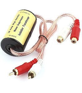
Audio Isolator
An Audio Isolator is similar to a DI Box, but it typically has no ground lift switch, because the two grounds are not connected. A transformer is used to couple the two audio signals. The one shown above is intended for stereo, but single-channel versions are common. Some pro audio techs just use bare audio transformers to save money; they work just as well
Some additional causes of noise and their cure can be found in the following TechHive video:
Audio Networks
In recent years, as audio systems have increased in complexity. and numerous components have been added, the necessity for connecting them together with a central control system has increased. For example, a large line array speaker system can have eight or more amplifiers installed in a high ceiling, and it is important to be able to monitor and control these amps from a remote location. To take advantage of the benefits of Category cable and the facts that such cables have been previously installed in some instances, various protocols for sending audio over IP networks have evolved. At present, three protocols have emerged as the most common.


